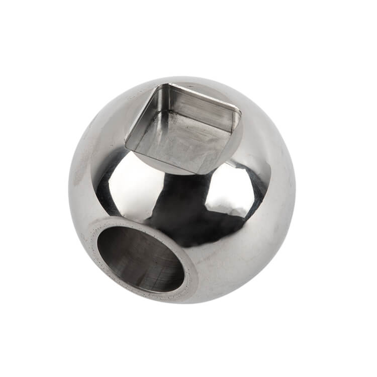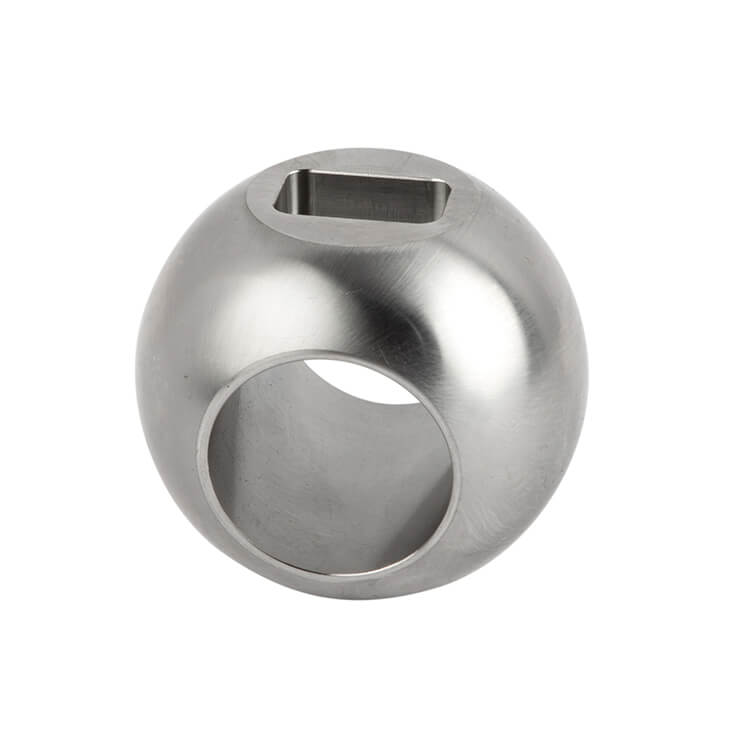


When your procurement team sources a ball valve body, the hydrostatic test report is often the first document your QA manager asks for. It is the moment the casting or forging proves it can hold pressure, resist deformation, and protect the pipeline downstream. Understanding the procedure behind that report helps your business avoid costly field failures, warranty claims, and rejected shipments.
In this guide, you will learn the complete ball valve body hydrostatic testing procedure used by manufacturers. We will walk through test pressure ratios, hold times, water-quality requirements, common failure modes, and acceptance criteria — all written for buyers, facility managers, and QA teams who need to verify quality without wading through pure engineering theory.
A ball valve body is the pressure boundary of the entire valve. Every port, wall thickness, weld, and flange connection must survive the rated pressure plus a safety margin. Hydrostatic testing uses water to apply that pressure and reveal leaks, cracks, porosity, or wall deformation before the valve body ever leaves the factory.
For your business, this matters because:
Need ball valve bodies with full test documentation?
GOTEB supplies ball valve bodies from 150LB to 2500LB with ±0.01mm dimensional control.
Most industrial ball valve bodies are tested to one of two standards, depending on the end market:
Both standards require the body to be tested at a pressure higher than its rated working pressure. The extra margin is what forces hidden defects to reveal themselves.
The table below shows the standard test-pressure multipliers applied to the rated pressure of the ball valve body.
| Test Type | API 598 Multiplier | Purpose |
|---|---|---|
| Shell Test (Body) | 1.5 × rated pressure | Verifies body wall strength and leak tightness of the pressure boundary |
| High-Pressure Seal Test | 1.1 × rated pressure | Checks seat-to-body sealing under operating pressure |
| Low-Pressure Seal Test | 5–7 psig (air) | Detects minor seat leaks that high pressure can mask |
Below is a practical reference for common pressure classes. Actual test pressure may be rounded to the nearest standard gauge increment used by your supplier.
| Pressure Class | Rated Pressure @ 100°F | Shell Test Pressure (1.5×) | Minimum Hold Time |
|---|---|---|---|
| Class 150 | 285 psig / 19.7 bar | 428 psig / 29.5 bar | 15 seconds |
| Class 300 | 740 psig / 51.0 bar | 1,110 psig / 76.5 bar | 60 seconds |
| Class 600 | 1,480 psig / 102 bar | 2,220 psig / 153 bar | 60 seconds |
| Class 900 | 2,220 psig / 153 bar | 3,330 psig / 230 bar | 120 seconds |
| Class 1500 | 3,705 psig / 255 bar | 5,558 psig / 383 bar | 120 seconds |
Note: Larger valve sizes and certain project specs may require longer hold times. Always confirm the test protocol in your purchase order.
Here is the procedure a manufacturer follows when testing a ball valve body before shipment.
The body is visually inspected for cracks, sand inclusions, machining marks, and damaged threads. All internal passages are flushed to remove chips, oil, and debris that could contaminate the test medium.
Blind flanges or test caps are bolted to the inlet and outlet ports. The body cavity is left open for filling and venting. At this stage, the ball, seats, and stem are usually removed so the test isolates the body itself.
The body is completely filled with clean water to eliminate trapped air. Air pockets compress during pressurization and can give false pressure-drop readings, so venting is critical.
A calibrated pump slowly raises the pressure to 1.5 times the rated pressure. The rate is controlled to avoid water hammer or sudden stress on the body walls.
The pressure is held for the required duration. Inspectors check every weld, flange face, casting surface, and threaded connection for visible leakage, sweating, or deformation. Pressure gauges are monitored for drop.
After acceptance, the body is slowly depressurized, drained, and dried. A corrosion inhibitor may be applied if the valve body will be stored before final assembly.
The test pressure, hold time, ambient temperature, water quality, and result are recorded on a traceable test certificate. Your QA team should keep this document with the valve’s material and inspection records.

The test medium is not “any water.” Using the wrong water can stain stainless steel, leave chloride deposits, or corrode the body before it ships.
| Parameter | Typical Requirement | Why It Matters |
|---|---|---|
| Chloride content | < 50 ppm for stainless steel | Prevents chloride stress corrosion cracking |
| pH | 6.0 – 8.0 | Avoids acidic or alkaline attack on metal surfaces |
| Suspended solids | Filtered / low | Prevents scoring of machined sealing surfaces |
| Temperature | Above dew point, typically 5–50°C | Avoids condensation and temperature-related pressure drift |
Not every body passes on the first attempt. Knowing the failure signature helps your business decide whether to reject, repair, or re-test.
| Failure Sign | Likely Cause | Typical Action |
|---|---|---|
| Visible water leak at body wall | Porosity, shrinkage cavity, or crack in casting | Reject or weld-repair per qualified WPS |
| Leak at flange face | Damaged sealing surface or uneven bolt torque | Re-machine face or re-torque test fixture |
| Pressure drop with no visible leak | Air trapped in cavity, gauge drift, or small weep | Re-vent, re-pressurize, and re-test |
| Body distortion or bulging | Insufficient wall thickness or wrong material grade | Reject; review design and material certificates |
| Leak at threaded connection | Thread damage or insufficient engagement | Re-cut or replace connection |
For severe erosion or wear-prone services, the right valve sphere hard facing options can extend service life after the body itself has passed hydrostatic testing.
Before you accept a shipment, verify that the test report contains at least the following fields:
Missing any of these items can delay commissioning or trigger third-party reinspection at your cost.

The shell test checks the body. The seat tests check sealing. Together they tell you whether the valve will perform in both directions. If your application requires tight shutoff in reverse flow, understanding bi-directional vs unidirectional sealing is just as important as the hydrostatic body test.
Similarly, if your system is sensitive to energy loss, low pressure drop helps the overall valve efficiency. You can read how this affects floating ball valve working efficiency in our related guide.
Hydrostatic testing proves that the valve body can safely contain pressure above its normal operating rating. It reveals casting defects, cracks, porosity, and inadequate wall thickness before the body is assembled into a finished valve.
Per API 598, the shell test pressure is typically 1.5 times the valve’s rated pressure at 100°F. For example, a Class 300 body rated at 740 psig is tested at approximately 1,110 psig.
Hold time depends on valve size and standard. Common durations range from 15 seconds for small valves to 120 seconds or more for large or high-pressure bodies. Project specs may require longer holds.
Clean, filtered water with low suspended solids and a neutral pH is standard. For stainless steel bodies, chloride content should stay below 50 ppm to prevent stress corrosion cracking.
Common failures include visible wall leakage from porosity, pressure drop from trapped air or small weeps, flange-face leaks, and body distortion. Each failure signature points to a different root cause in material, machining, or test setup.
Yes. In fact, the shell test is normally performed with internal trim removed so the test isolates the pressure boundary of the body itself. Seat and seal tests are performed separately after assembly.
No, when performed correctly at standard test pressure and hold time, hydrostatic testing does not damage a sound valve body. It is a non-destructive validation method used across the valve industry.
Ready to source tested ball valve bodies?
Send us your pressure class, material, and quantity. GOTEB will quote valve bodies.
Hydrostatic testing is not just a factory checkbox — it is the proof that your ball valve body will hold pressure when it matters. By understanding the pressure ratios, hold times, water requirements, and acceptance criteria, your procurement and QA teams can read test reports with confidence and reject substandard components before they reach your project site.


 Optimized by Seraphinite Accelerator