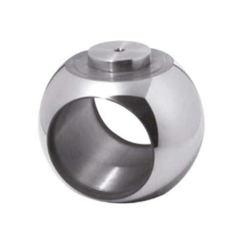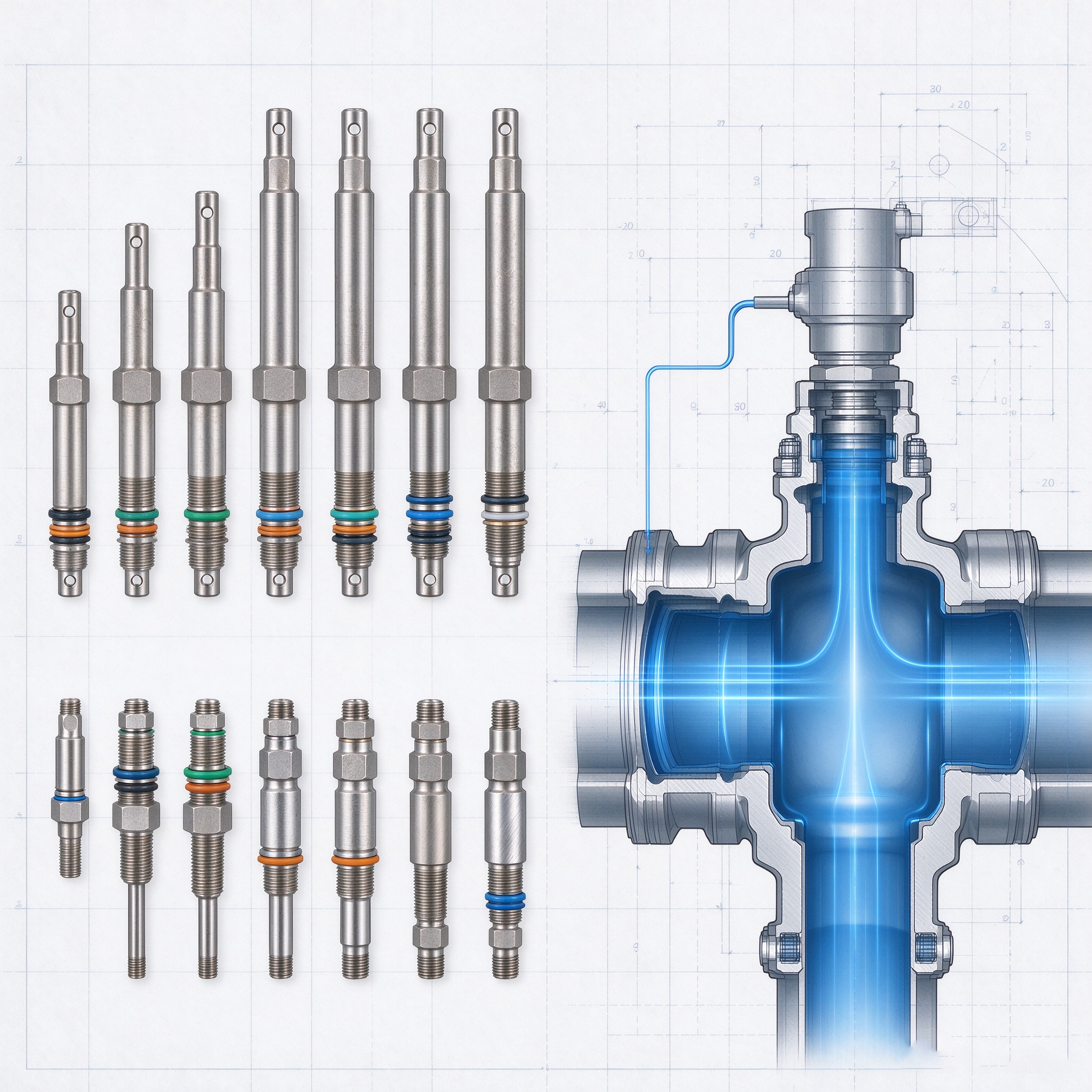


Inspect a ball valve body before assembly in seven stages — document review, visual examination, dimensional check, wall thickness verification, NDT of the pressure boundary, surface finish and cleanliness check, and a shell pressure test. Each stage has a defined acceptance criterion tied to the drawing, the pressure class standard and the customer specification. Any body that fails a stage should be quarantined with a non-conformance record rather than moved forward to keep the assembly line moving.
Most valve failures that get blamed on seats, packing or assembly practice are actually inherited from a body that was accepted with a defect. Once the ball is installed and the bonnet is torqued, that defect is invisible until the valve is in the line.

Inspection starts with paperwork, because paperwork tells you what you should expect to see. If the documents are incomplete, the physical inspection cannot compensate.
Check that the heat number on the certificate matches the heat number stamped or tagged on the body. A mismatch is not a paperwork error — it means the traceability chain is broken, and no downstream inspection can repair it.
Visual inspection catches the defects that no gauge will find: casting skin defects, weld spatter, tool marks in sealing areas, corrosion during storage, and handling damage on flange faces.
Work through the body systematically rather than glancing at it:
Lighting matters more than most inspectors admit. A directional lamp at a low angle reveals surface discontinuities that diffuse overhead light hides completely.
Dimensional checks confirm that the body will assemble and that it will fit the pipeline. The critical characteristics are not the same as the ones on a general machining drawing.
| Characteristic | Why it matters | Typical method |
|---|---|---|
| Bore diameter and roundness | Ball clearance, seat load, flow area | Three-point bore gauge, CMM |
| Seat pocket diameter, depth, cone angle | Seat fit and preload | Bore gauge, depth micrometer, profile projector |
| Concentricity of the two seat pockets | Torque balance, even seat wear | Mandrel through both pockets, CMM |
| Face-to-face length | Fit in the pipeline, gasket compression | Vernier or height gauge on a surface plate |
| Flange diameter, bolt circle, bolt hole size and count | Mating with the pipe flange | Caliper, bolt circle template, CMM |
| Flange face flatness, parallelism, squareness to bore | Gasket seating and bolt load distribution | Straight edge and feeler gauge, dial indicator |
| Stem bore position and squareness | Stem alignment, packing life | CMM, mandrel with dial indicator |
Record the actual values, not just pass/fail. A body that is consistently at the edge of tolerance tells you something about the supplier’s process capability, and that is the information you need before placing the next order.

Ultrasonic thickness measurement confirms that the casting or forging has enough wall to meet the pressure class after machining. It is the only practical way to check the cavity and the flange transition without cutting the body open.
Take readings at a fixed set of points — typically four around the bore, four around the cavity, and four at each flange hub — and record them on a sketch so the next inspection uses the same locations. Compare the minimum reading against the calculated minimum wall for the material and pressure class, not against the nominal drawing dimension.
Any reading below minimum is a reject, regardless of how the body performs in a pressure test. A thin wall does not fail gradually; it fails when the pressure spike arrives.
Non-destructive testing on the body before assembly should target the areas where defects hide: section transitions, seat pocket walls, weld repairs and the flange hub.
Acceptance criteria should reference a recognised standard — ASME Section V for the technique, and the applicable product standard for acceptance levels. “Inspected and accepted” without a stated acceptance level is not an inspection, it is an opinion.
Surface finish affects sealing, coating adhesion and corrosion resistance. Check the flange sealing face against the specified Ra range, and the ball-to-seat path and stem bore against their own requirements.
Cleanliness is the stage most often skipped and the one that causes the most assembly problems. A body that still carries machining chips in the seat pocket will damage the seat during assembly, and the damage will be attributed to the seat supplier. Verify that the body has been deburred, degreased, dried and capped or plugged for transport.
For stainless bodies, confirm that passivation was performed after machining. Free iron left on the surface will show up as rust blooms in storage, and buyers will reasonably assume the material is wrong.
The shell test proves the pressure boundary. It is performed with the body closed off, at 1.5 times the rated pressure for the applicable standard, held for the specified duration, with no leakage or permanent deformation.
Two practical points decide whether the test is meaningful. First, the test pressure must be measured at the body, not at the pump. Second, the body should be dry on the outside before testing, so that a weep is visible rather than masked by residual water. Test water chemistry matters as well — chlorides in test water can initiate pitting on stainless bodies that are not drained and dried afterwards.
The procedure and pass criteria are set out in detail in ball valve body hydrostatic testing.

Want bodies that arrive ready for your assembly line?
Tell us your incoming inspection criteria and we will build the acceptance plan into production — dimensional report, wall thickness map, NDT records, passivation confirmation and shell test certificate, all traceable to the heat number. That removes the rework loop between goods-in and assembly.
| Check | Acceptance criterion | Action if failed |
|---|---|---|
| Heat number traceability | Certificate matches body marking | Quarantine; request re-identification |
| Visual surface | No cracks, cold shuts, laps, scores in sealing areas | Reject or evaluate per engineering disposition |
| Bore and seat pocket dimensions | Within drawing tolerance, typically ±0.01 mm | Reject; do not attempt to compensate with seat thickness |
| Seat pocket concentricity | Per drawing; mandrel passes through both pockets | Reject |
| Wall thickness | Not less than calculated minimum for the class | Reject; no repair possible |
| Surface finish | Within specified Ra; no tool marks in sealing areas | Rework if wall allows, otherwise reject |
| Cleanliness | No chips, debris, oil or water in cavity and pockets | Clean and re-inspect |
| Shell test | 1.5× rated pressure, specified duration, no leak | Reject; investigate casting or weld |
Pressure-boundary characteristics should be inspected on 100% of bodies: shell test, visual, and any characteristic that would cause a leak or an assembly failure. Characteristics that are process-controlled and stable — marking legibility, paint thickness, packaging — can be sampled with an AQL plan.
For first articles and new suppliers, inspect everything for the first three lots, then reduce to a sampling plan once process capability is demonstrated. If a lot fails, return to 100% inspection until three consecutive lots pass.
Rust on machined stainless surfaces. Passivation skipped or iron contamination from tooling — a process control issue, not a material issue.
Chips in the seat pocket. Inadequate cleaning after machining; will damage seats during assembly.
Seat pocket depth consistently at the low limit. Tool wear not compensated — expect seat over-compression and high torque.
Flange face scores. Handling damage from stacking without protection; causes joint leaks that get blamed on gaskets.
Wall thickness variation around the cavity. Core shift in the casting; check against the pattern and the foundry’s process control.
Body joint faces that do not mate cleanly. Machining or handling damage; will leak at pressure after assembly.
Each of these findings points at a supplier process, not at an individual part. Recording them by category is what turns incoming inspection into supplier development. If you assemble valves in-house, the same records explain the defects covered in common assembly errors that damage body components.
What should be inspected on a ball valve body before assembly?
Seven things: documentation and heat number traceability, visual surface condition, critical dimensions (bore, seat pockets, flange faces, face-to-face length), wall thickness, NDT of the pressure boundary, surface finish and cleanliness, and a shell pressure test. Skipping any one of these allows a defect through that will be hidden once the ball and bonnet are installed.
Should every body be pressure tested before assembly?
Yes for the shell test. It is the only check that proves the pressure boundary as manufactured, and it is quick relative to the cost of discovering a leak after assembly and painting. Bodies that will be assembled into valves that are themselves shell tested may be tested at body stage and again at valve stage, depending on the quality plan.
How do I check seat pocket concentricity without a CMM?
Use a mandrel or a precision bar that passes through both seat pockets. If it enters freely and seats fully in both, concentricity is within the clearance built into the mandrel. For a numeric value, mount a dial indicator on the mandrel and rotate it in each pocket to read the total indicated runout.
What is an acceptable wall thickness for a ball valve body?
It must be at least the minimum calculated thickness for the material and pressure class, typically per ASME B16.34, plus any corrosion allowance specified by the purchaser. Measure at the cavity and flange transitions, not just at the bore, because those are the areas where castings run thin and where corrosion concentrates.
Why does a new stainless body rust in the warehouse?
Free iron contamination from machining, blasting media or handling, combined with moisture in storage. The stainless steel itself is not corroding; the embedded iron particles are. Passivation after machining per ASTM A967 removes the contamination, and dry, capped storage prevents the moisture that starts the rust.
What records should be kept with each body?
Material certificate with heat number, dimensional report with actual values, wall thickness map, NDT reports with method and acceptance level, weld repair documentation if applicable, shell test certificate, and the inspector’s identification and date. Keep them linked to the body’s serial or heat number so a field issue can be traced to a production lot.


 Optimized by Seraphinite Accelerator