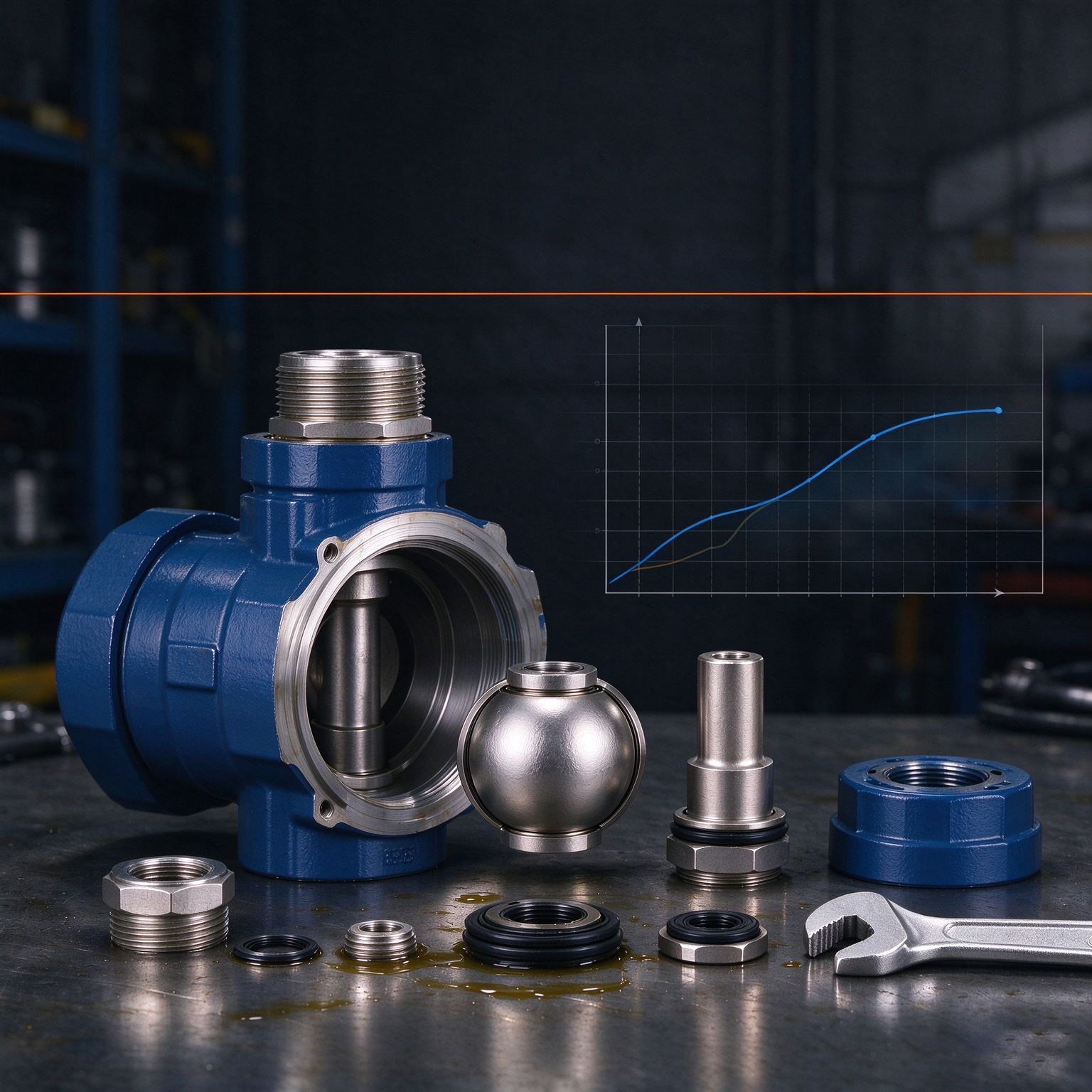


Material and coating get most of the attention on a valve bill of materials, but a Customized Ball Valve Ball only performs if it is machined accurately. The spherical surface must sit evenly on the seats, the port must line up with the end connections, and the stem or trunnion features must transmit torque without shifting the ball off center. When any of those geometries is loose, the valve leaks, torque rises, and the seats wear earlier than assumed.
Precision machining is therefore a performance specification, not a workshop preference. For OEM custom balls, dimensional tolerances are commonly controlled within ±0.01 mm, and that figure only has meaning if it is tied to sphericity, port alignment, surface finish, and the condition of the ball after any coating or hard facing. This article explains how those controls improve sealing, reduce torque, and extend seat life, and what to put on the drawing so the manufacturer can deliver them.

A ball valve seals when a continuous contact band forms between the sphere and the seats. If the sphere is out of round, oversized, or undersized, that band becomes uneven. Fluid finds a path at the light-contact zone, and the opposite side of the seat is overloaded. The same error increases breakaway and running torque, because the ball is being forced into a seat that no longer matches its shape.
These problems often appear first at hydrostatic or seat-leakage testing, or after a short period of cycling, rather than as an obvious “wrong diameter” at incoming inspection. A ball can be within a loose commercial diameter tolerance and still be a poor sphere, which is why custom-ball drawings should control more than a single outside diameter.
The duty amplifies the effect. High-pressure classes, up to Class 2500 (2500LB), increase seat load, and high temperature changes fit as the ball and seats expand. Corrosive or abrasive media attack any gap or rough patch more quickly.
A stated tolerance of ±0.01 mm is a tight dimensional envelope for a valve sphere. Used correctly, it limits how far the finished diameter, and related linear features, may depart from the drawing. That control helps the ball enter the seats with a predictable interference or clearance, which is essential for both floating and trunnion designs.
It is not, by itself, a complete quality definition. Buyers sometimes write “±0.01 mm” on an inquiry and leave sphericity, port position, and stem-slot location unspecified. A ball can then meet the diameter tolerance and still have a port that is off-center, a stem slot that cocks the ball, or a local lobe that leaks. Specify which dimensions carry the tight tolerance: spherical diameter, trunnion diameters, stem-interface features, and any critical lengths or widths.
Also state when the tolerance is measured. If the ball will be coated or hard-faced—ENP, TCC, Stellite, or another treatment—the overlay adds thickness. The useful requirement is usually the finished, coated, and lapped condition, because that is the geometry the seats will see. If you need a machining allowance before coating, say so, and make it clear that the ±0.01 mm limit applies after final finishing.
Sphericity describes how closely the functional surface matches a true sphere. For sealing, it is often more important than a single diameter reading. A slightly oval or lobed ball concentrates contact on high spots. Soft seats such as PTFE, reinforced PTFE, or PPL can extrude or wear at those spots; metal seats can leak or gall.
If your valve standard or in-house specification already defines a sphericity or roundness limit, put that value on the drawing next to the diameter tolerance. If you do not have a number, ask the manufacturer to propose one consistent with the seat type and leakage class, and to show how they will measure it. Sphericity should be inspected on the sealing zone, not only on a convenient land away from the port edges.
Port edges themselves need attention. A sharp or irregular port intersection can cut a soft seat as the ball rotates, and it can be a weak point for coating chipping. A controlled edge break or specified radius, blended into the spherical surface, is part of precision machining.
Flow and torque depend on more than a round sphere. The through-port must be correctly sized and aligned so that, in the open position, it matches the valve bore. For a reduced-bore or characterized port, including a V-segment or V-port ball, the port geometry is the flow characteristic of the valve. Angular error in the port, or between the port and the stem slot, shows up as a flow curve that does not match the design, or as a ball that is not truly closed when the actuator hits its stop.
Stem-interface features—slots, tabs, pin holes, or an integral valve-ball-with-stem design—must be located relative to the port and the sphere center. A misplaced slot puts a side load on the stem and tilts the ball in the seats. In a trunnion-mounted custom ball, trunnion diameters and their coaxiality with the sphere axis control support under pressure; in a floating design, the sphere and stem slot must still allow the ball to shift downstream onto the seat in a controlled way.
Three-way balls, hollow balls, and plate balls add further datums—intersecting ports, cavity walls, or flats—that must stay true to the spherical sealing surface. A 2D drawing plus a 3D model, with clearly defined datums, helps prevent a first article that looks right and assembles wrong.
Dimensional accuracy without an appropriate surface finish still produces a poor valve. A rough or inconsistent spherical surface increases friction, raises torque, and creates local leak paths. For soft-seated valves, a smooth, uniform lapped surface is typically required so the polymer can form a tight band without being shaved. For metal-seated pairs, the finish and the hard-facing texture must be compatible so the ball does not tear the seat facing or fail to bed in.
Lapping and polishing are therefore part of the machining sequence, not an afterthought, and should be planned around the coating. Some hard facings are finished by grinding and lapping after deposit; a coating applied to an already-final sphere can change both thickness and roughness. Specify the required surface roughness on the sealing sphere, say whether it applies after coating, and mark any different requirements on the port bore or non-sealing areas.
Burrs, grinding marks, and interrupted finish at the port edges are common sources of early seat wear, so incoming inspection should include a visual and roughness check of the sealing band and port intersections, not only a diameter measurement.
Taken together, tight diameter control, sphericity, aligned ports and stem features, and a specified lapped finish improve four performance outcomes.
First, leakage is reduced because the seat contact band is continuous and correctly loaded. Second, operating torque is more stable, which matters for actuator sizing and frequent cycling. Third, seat life is extended, because high spots and rough patches are no longer wearing the PTFE, PPL, or metal facing on every stroke. Fourth, assembly and testing become more predictable: a ball that matches the drawing is less likely to need selective fitting or to fail a hydrostatic test.
These gains are why a precision-machined custom ball is often specified instead of a loosely tolerated stock sphere, especially in high-temperature, high-pressure, or corrosive media, or when the geometry itself is non-standard. Precision machining does not replace correct material and coating selection, but it is what allows those choices to work as designed.
A tight tolerance is only useful if it can be verified. Ask for a dimensional inspection report covering spherical diameter, sphericity or roundness of the sealing surface, port position and size, and stem or trunnion features. Where coating or hard facing is applied, include thickness, final roughness, and hardness when that is part of the specification.
Define the inspection condition—after final machining and finishing, and after coating if applicable. For a first-time custom geometry, a first-article inspection is often justified before you release the full quantity.
If you will also purchase seats from the same manufacturer, consider inspecting the ball and seat as a pair. A report that the ball is within ±0.01 mm is necessary, but a contact pattern or seat-leakage result on the assembled pair is a stronger criterion for critical valves.
Precision machining is how a Customized Ball Valve Ball turns a drawing into a part that seals, cycles, and lasts. A diameter tolerance controlled within ±0.01 mm is a starting point. Sphericity, port and stem alignment, edge condition, and a specified surface finish after any coating are what actually reduce leakage, torque, and seat wear.
Put those requirements on the drawing, state whether they apply after hard facing, and require inspection records that prove them. For OEM balls in classes from 150LB to 2500LB, including V-segment, three-way, and integral-stem designs, share the finished-geometry specification with a manufacturer that treats custom spheres as a core product, such as the customized ball valve balls available from GOTEB, and approve a first article before volume production.
It keeps the sphere round and to size, aligns the port and stem features, and produces a consistent sealing finish. The practical results are lower leakage, more stable operating torque, and less seat wear during cycling.
That tolerance controls dimensional variation, but it does not automatically control sphericity, port position, or surface roughness. Those characteristics should be specified and inspected as well, especially on the sealing band.
They should be defined for the condition the seats will see, usually after coating, grinding, and lapping. If a pre-coat machining allowance is needed, state both the in-process size and the finished tolerance.
Misalignment can prevent full opening or tight shutoff, distort the flow characteristic of a V-port ball, and tilt the sphere in the seats, causing leakage, higher torque, and uneven seat wear.
A dimensional report covering diameter, sphericity, port and stem features, plus roughness and coating thickness when applicable. For a new design, add first-article inspection, and consider pair testing if the seat is supplied with the ball.


 Optimized by Seraphinite Accelerator