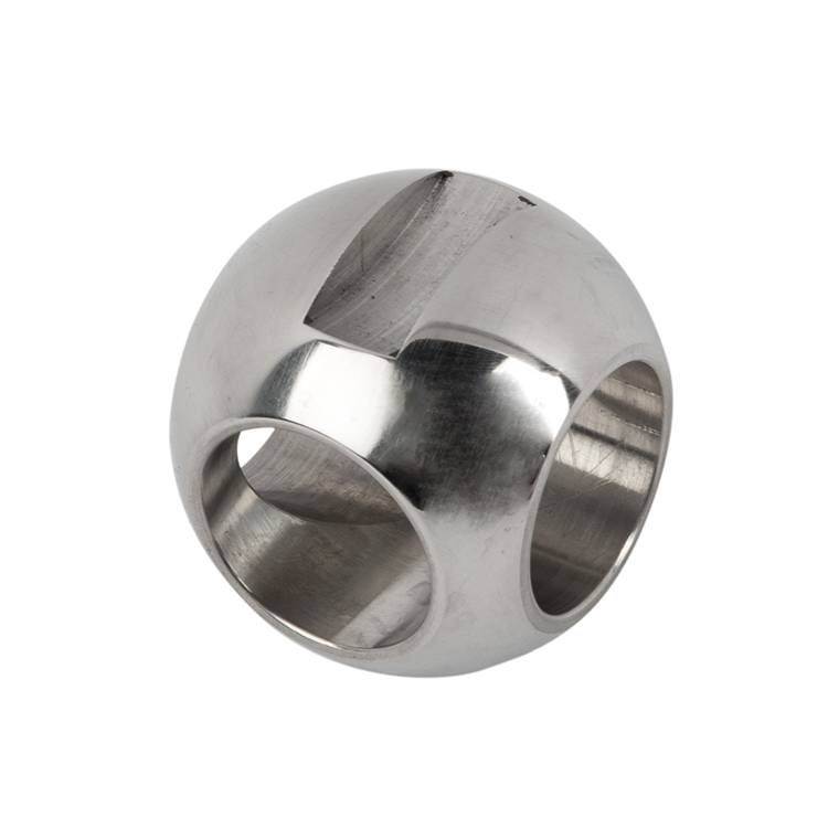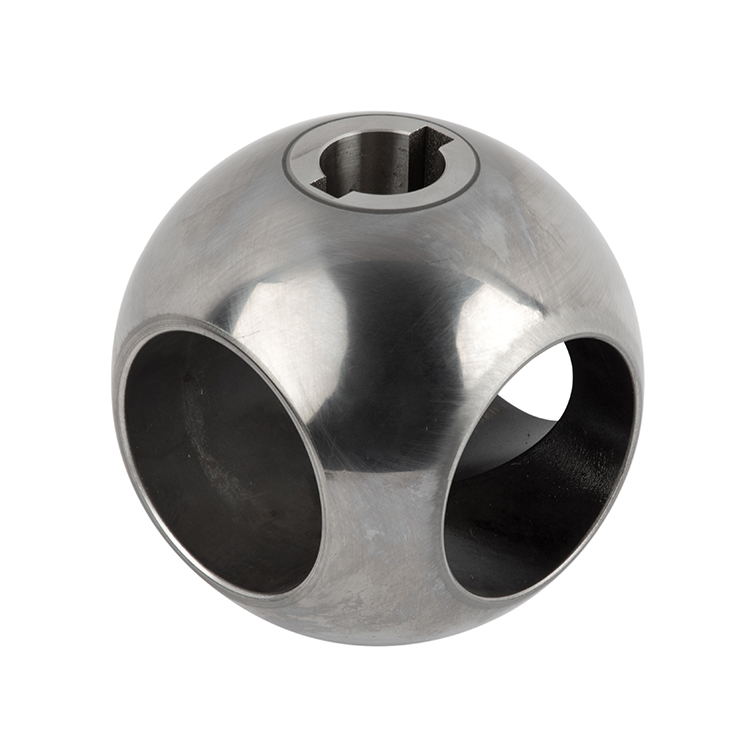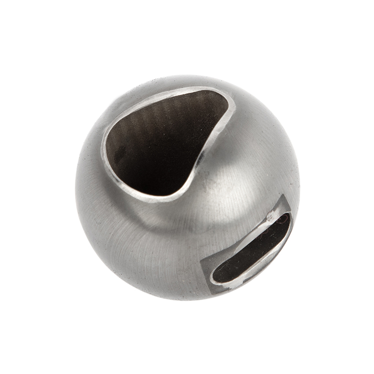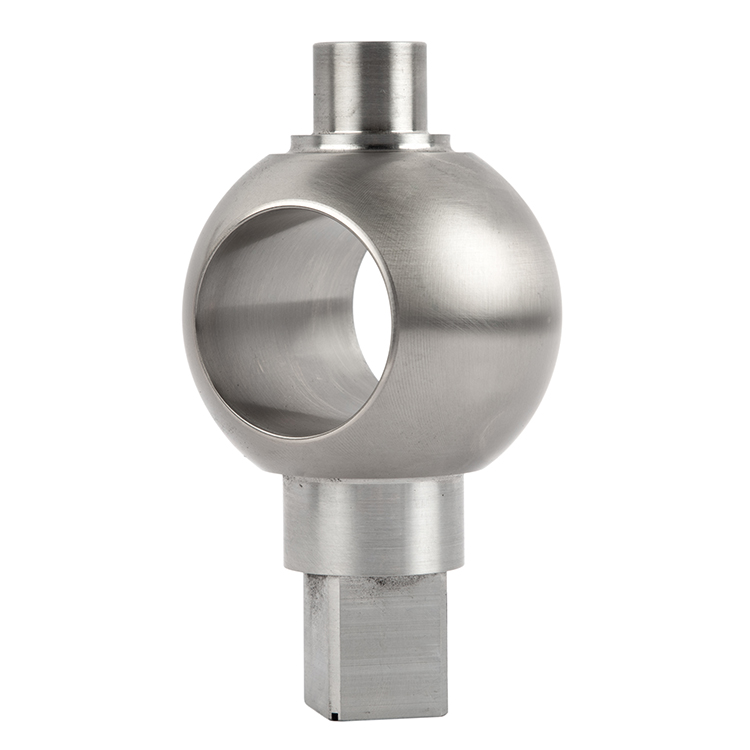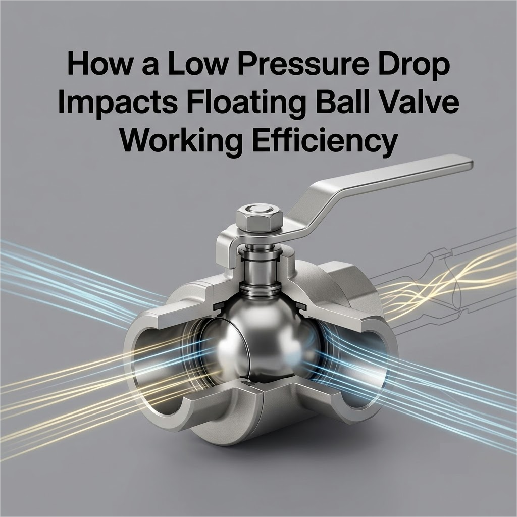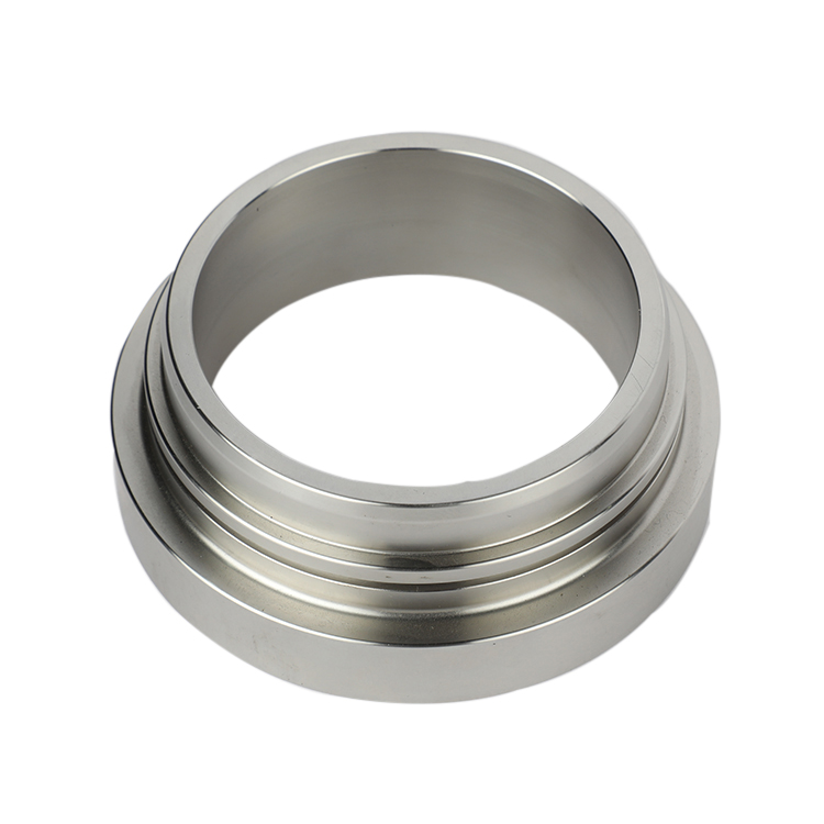


When your business sources quarter-turn hardware, you might wonder: do ball valves have a flow direction? Assuming every valve handles pipeline pressure identically from both sides is a common trap. Sourcing errors lead to immediate seat leakage. The real answer lies deep within the interior component layout, where the precise match between the ball core and seat configuration sets the fluid rules.
In industrial piping, ball valve flow direction refers to the specific orientation fluid must take when passing through the internal flow channel.
The Path of Least Resistance: It marks the path where line pressure works with the internal parts rather than fighting against them.
Pressure Vectors: When fluid enters the valve, it creates immense physical forces against the internal sphere. The orientation determines how these forces are distributed across your sealing components.
System Integrity: Matching your pipeline layout to the intended design flow keeps your systems running smoothly without dropping pressure.
If you ask an experienced engineer, are ball valves directional, the answer is rarely a simple yes or no. It entirely depends on how the inner components are built.
The Component Split: Ball valves are broadly split into two main mechanical categories based on how the central sphere is supported.
Symmetric Designs: Some setups use perfectly mirrored parts on both sides, allowing fluid to travel back and forth with zero drop in sealing performance.
Asymmetric Designs: Other setups rely on specialized, one-way seat dynamics that require fluid to enter from a single designated port to force the seal shut.
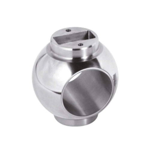
Standard floating systems are the most common configurations where the internal sphere is not held rigidly at the bottom.
The Downstream Shift: In a standard floating setup, the ball connects only to the top drive stem. When fluid pressure enters the port, it pushes the ball physically downstream.
Natural Dual Barriers: Because the ball slides slightly forward under pressure, it jams itself tightly into the opposite soft plastic seat ring. This automatic mechanical shift creates a highly reliable bidirectional ball valve that seals perfectly from either port.
Equal Wear: Since fluid can enter from either side, your assembly team can install these units without worrying about reverse piping layouts, as both seat inserts share the mechanical load equally over time.
When you move into high-pressure industrial lines, the floating mechanism becomes dangerous because the fluid force is too massive. This forces a shift to heavy-duty fixed-axis setups.
The Dead-Locked Axis: In a trunnion layout, the massive metal sphere is pinned firmly by an upper drive journal and a lower trunnion pin. It cannot budge or slide downstream even a fraction of a millimeter.
Dynamic Sliding Seats: Because the ball cannot move, the seat rings must do all the traveling. They use tiny springs behind the metal housings to actively push forward against the ball face.
The Single-Piston Trap: If the system uses a Single Piston Effect (SPE) seat configuration on the inlet side but a different style on the out-port, it creates a strict unidirectional ball valve. Fluid pressure must enter from the designated upstream side to help cram the seat tighter against the ball.
The Blind Spot: If your team installs this configuration backward, line pressure will slip behind the seat ring and lift it physically away from the sphere, causing an instant internal bypass. Understanding these critical trunnion ball valve direction traits is vital before finalizing your component procurement contracts.
Preventing field disasters comes down to training your quality inspectors to read the mechanical hardware before it leaves the warehouse floor.
Understanding ball valve open and closed positions is your first line of defense during assembly tracking.
The Ball Valve Open Position: In a full ball valve open position, the internal machined bore aligns perfectly flush with the pipeline axis, allowing fluid to rush through with zero restriction.
The Ball Valve Closed Position: Turning the lever or actuator exactly 90 degrees shifts the mechanism to the ball valve closed position, rotating the solid, polished face of the sphere directly in front of the seat faces to block the path.
Stem Alignment Indicators: Always check the small indicator pin or notch on top of the drive stem; if it runs parallel to the pipe, you are open, and if it runs crosswise, you are closed.
External markings on the forged steel ball valve body provide immediate clues for your installation crew.
The Directional Arrow: A unidirectional valve will feature a permanent, raised arrow stamped into the metal body casing, showing your team exactly which way the fluid must travel.
No Markings: If the valve housing is completely smooth on both sides with no directional stamps, it generally indicates a standard, symmetric floating system built for dual-direction flow.
Tag Data: Always cross-reference the manufacturer metal data tag for specific API or ISO testing stamps that denote pressure limits and orientation rules.
When external tags are missing, a quick look inside the port reveals the true component design.
Asymmetric Seats: Look closely past the bore; if the upstream seat ring features visible coil springs but the downstream seat uses a thick, rigid retaining wall, you are holding a directional unit.
The Mirror Test: Symmetric floating units look identical from both ends, utilizing matching polymer rings embedded evenly on both sides of the ball.
Internal Clearances: Measuring the physical clearance between the seat housing and the valve body helps verify if the seats are designed to slide or stay locked. Reviewing how overall ball valve parts and function alter fluid tracking gives your team a complete roadmap for diagnosing these internal layouts.
When components are misaligned during a rushed field installation, the internal parts will start showing specific failure symptoms.
| Mechanical Symptom | Root Internal Cause | Operational Impact on the Line |
| Upstream Spring Fatigue | Back-pressure fluid forces enter the wrong cavity and compress the springs past their design limit. | The seat loses its pre-load force, causing low-pressure seat leaks. |
| Asymmetric Wear Scars | The fixed sphere tilts slightly against a misaligned seat track during rotation. | Sudden operational torque spikes that can stall your automated actuators. |
| Instant Low-Pressure Bypass | Reverse line fluid lifts the sliding seat ring completely away from the polished ball face. | Immediate factory or field hydro-static pressure testing failures. |
Do ball valves have a flow direction arrow stamped permanently on the valve body?
Only unidirectional valves feature a permanent flow arrow; standard bidirectional floating ball valves usually have completely blank bodies.
What internal component makes a trunnion mounted assembly a unidirectional ball valve?
An asymmetric seat design, such as an SPE seat layout on one side, forces a single directional flow rule.
How can you tell ball valve open and closed positions if the lever handle is missing?
Check the flat notch on the drive stem; it aligns parallel to the pipeline when open and crosswise when closed.
Why does a bidirectional ball valve still require high-precision surface roughness on the sphere?
Low roughness prevents the rotating ball face from scratching or tearing the soft plastic seats during dual-direction pressure shifts.
What happens to internal seat springs if fluid enters a unidirectional valve from the wrong side?
The fluid pressure compresses the springs completely or bypasses them, lifting the seat face away and causing immediate internal leaks.
Are all floating ball valves naturally bidirectional ball valve setups?
Yes, standard floating designs rely on the ball shifting downstream to seal, allowing them to handle flow from either direction.
Can an operator change a unidirectional valve into a bidirectional ball valve in the field?
No, you cannot alter the orientation without completely swapping out the internal seat rings and spring housings in a workshop.
What is the main danger of operating a valve halfway between the ball valve open position and closed position?
Throttling halfway exposes the polished sphere face and soft seat edges to high-velocity erosion, destroying your tight sealing tolerances.
Mastering ball valve flow direction requires looking past external markings and understanding the internal sphere-to-seat pairing. Balancing floating designs with active, spring-loaded trunnion seats keeps your assembly lines safe and leak-free. Contact GOTEB today to submit your engineering drawings, request technical quotes, or source precision-machined component kits built for long-term pipeline reliability.


 Optimized by Seraphinite Accelerator