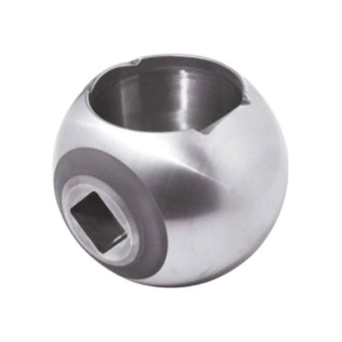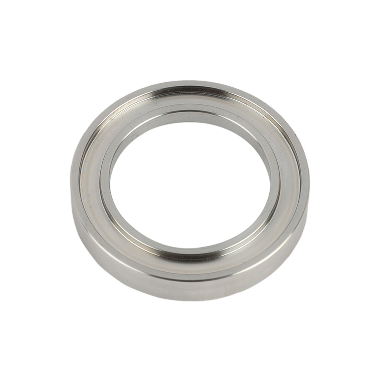


Ball valve body machining controls four things that decide valve performance — the roundness and alignment of the bore, the concentricity and angle of the seat pockets, the flatness and parallelism of the flange faces, and the surface roughness of every sealing surface. When those four are held inside tolerance, the valve seals at its rated pressure class, turns at a predictable torque, and the seats wear evenly. When they drift, the same design leaks, jams, or eats actuators.
A ball valve body is the pressure boundary and the geometric reference for every other component in the valve. The ball, seats, stem and bonnet are all positioned relative to surfaces that a machinist cut. That is why machining is not a finishing step — it is the step that decides whether the assembly works.
This guide breaks down which machining characteristics matter, how each one shows up as a performance problem in the field, and what to write into a purchase order so the parts you receive can actually be assembled and tested.

Not every dimension on a valve body drawing carries the same weight. Six features drive performance directly, and they deserve the tightest tolerances and the most inspection time.
| Machined feature | What it controls | Typical failure if out of tolerance |
|---|---|---|
| Bore diameter, roundness, straightness | Flow area, ball clearance, seat compression | High torque, seat extrusion, internal leakage |
| Seat pocket diameter, depth and angle | Seat fit, contact stress, ball-to-seat preload | Seat rocking, leakage at low pressure, premature wear |
| Flange face flatness and parallelism | Gasket seating, bolt preload distribution | Joint leakage, gasket creep, flange cracking |
| Face-to-face length and flange squareness | Fit in the pipeline, pipe alignment | Installation stress, bending load on the body |
| Stem bore and packing pocket | Stem alignment, packing compression | Stem binding, fugitive emissions, gland leaks |
| Surface roughness of sealing faces | Seal contact, friction, coating adhesion | Scratch marks on the ball, inconsistent torque |
The bore is the path the medium takes and the space the ball sits in. A bore that is out of round by 0.02 mm looks fine to the eye and measures fine on a two-point micrometer, but it changes how the seats load the ball.
On a floating ball design, line pressure pushes the ball downstream into the seat. If the bore is oval or tapered, the ball contacts the seat unevenly. One side carries most of the sealing load, the other side barely touches. The result is a valve that passes a hydrostatic shell test, passes a low-pressure seat test on the bench, and then leaks after a few hundred cycles because the high-load side of the seat has extruded.
On a trunnion mounted design the effect is different but just as expensive. The ball is held by the stem and the trunnion bearing, so bore misalignment translates into torque variation. The actuator has to be sized for the worst position, which usually means buying a larger, more expensive actuator than the valve actually needs.
Good practice is to bore in two stages: a roughing pass that removes most of the material, then a semi-finish and finish pass after stress relief, so the bore does not move when residual stresses redistribute. GOTEB holds dimensional tolerances within ±0.01 mm on body bores and seat pockets, with roundness verified on a three-point bore gauge or a coordinate measuring machine rather than a caliper.

The seat pocket is where machining tolerance becomes sealing performance. Three parameters matter: the diameter of the pocket, its depth relative to the ball centerline, and the angle of the sealing cone.
If the pocket is too shallow, the seat is over-compressed during assembly. Elastomeric seats take a compression set and lose resilience; PTFE seats cold-flow into the clearance gap. If the pocket is too deep, the seat does not touch the ball at low pressure, and the valve only seals once line pressure forces the ball into contact — which fails the low-pressure seat test that most specifications require.
Concentricity between the two seat pockets is equally important. In a split body valve, each pocket is machined in a different half. If the two halves are machined in separate setups without a common reference, the ball centerlines do not coincide, and the ball rides against one seat harder than the other. This is one of the most common root causes of “the valve turns hard in one direction only.”
The practical control is to machine both seat pockets from the same datum, or to finish-machine the assembled body halves as a pair. Either approach works; what does not work is assuming that two independently machined halves will line up because both were programmed from the same drawing.
Body machining also sets up the pipe joint, and pipe joint failures are usually blamed on gaskets. In reality, a flange face that is not flat, or two faces that are not parallel, will leak no matter which gasket you install.
For raised-face flanges, the sealing face should be machined to the surface finish specified by ASME B16.5 — typically 125 to 250 µin Ra (3.2 to 6.3 µm Ra) with a concentric or phonographic finish. A face that is too rough leaks through the tool marks. A face that is too smooth (mirror finish) removes the radial grooves the gasket needs to grip, and the gasket creeps under thermal cycling.
Parallelism between the two flange faces controls how the bolt load distributes. If the faces are out of parallel by 0.2 mm across a 200 mm flange, the bolts nearest the gap carry far more load than the others. The gasket compresses unevenly, and the joint leaks at the low-load side — usually after the first thermal cycle, which is why these failures appear in the field rather than in the factory test.
Perpendicularity of the flange face to the bore matters on both counts: it keeps the gasket seating area square to the pipe axis, and it prevents bending moments from being transferred into the body wall when the mating flanges are tightened.

Surface roughness is the most under-specified machining requirement on valve body drawings, and it is the one that shows up fastest in service.
For the ball-to-seat contact path, a roughness of Ra 0.4 to 0.8 µm supports a consistent film of medium between the ball and the seat and keeps friction predictable. Rougher surfaces (Ra 3.2 µm and above) act like a file: they polish the ball, generate wear debris, and scratch the seat. Smoother surfaces than necessary increase cost without improving sealing, because the seat material, not the steel, controls contact.
For the stem bore and packing pocket, roughness controls both friction and sealing. A rough stem bore wears the packing rings from the inside and creates a leak path along the stem — the classic “drip from the gland that never stops” complaint. Roughness in the range of Ra 0.4 to 1.6 µm is normal for these surfaces, with the exact value set by the packing type and the stem coating.
Roughness also decides whether a surface treatment will work. Electroless nickel, hard chrome and sprayed carbide coatings need a controlled anchor profile. A polished surface with no profile produces a coating that blisters or flakes; an excessively rough surface produces a coating with peaks that break through and corrode first.
The stem is the only part of a ball valve that moves every time the valve is operated, and the body has to hold it in line. The stem bore must be coaxial with the ball’s stem slot and square to the bonnet mounting face. If it is not, the stem bends slightly with every quarter turn.
A bent stem concentrates stress at the packing area and at the stem-to-ball connection. Operators notice it as increasing torque, then as a valve that will not fully open, then as a broken stem. Because the failure happens inside the pressure boundary, the consequences go beyond a maintenance ticket.
Machining the bonnet register (the counterbore or spigot that centers the bonnet on the body) in the same setup as the stem bore is the cheapest way to guarantee alignment. When those two features are machined in separate operations, the accumulated stack-up can exceed the clearance designed into the stem, and the assembly relies on bolt torque to pull the parts into line — which distorts the body and preloads the stem.
On split body and three-piece designs, the body joint is a second sealing boundary, and its machining quality decides whether that boundary holds.
Two parameters matter: the flatness of each joint face and the alignment of the bore across the joint. Flatness controls gasket compression; bore alignment controls whether the ball and seats sit on a common centerline once the halves are bolted together.
A common field failure is a body joint that weeps only at high pressure. The gasket is blamed first, then replaced, then the joint weeps again. The actual cause is usually a joint face that was machined with a slight dish or taper — flat enough to seal at low pressure, not flat enough to keep the gasket uniformly loaded when the body strains under pressure.
The fix is procedural rather than exotic: finish-machine the joint faces in matched pairs, check flatness with a straight edge and feeler gauge or on a surface plate, and verify bore alignment with a mandrel or laser before the halves go to assembly.
Machining problems are cheaper to fix at the drawing stage
Send us your body drawing with the pressure class, material grade and sealing requirement. Our engineering team reviews the tolerance stack, seat pocket geometry and flange finish before quoting, and tells you which dimensions need tightening — and which ones you are paying for unnecessarily. Production covers NPS 2 to NPS 40 (DN50 to DN1000), Class 150 to 2500, in A105, LF2, F304, F316, F51/F53/F55, 17-4PH, Inconel and Monel.
Buyers rarely see a machining report. They see the consequences, usually in one of these forms:
Seat leakage at low pressure only. Seat pocket depth or concentricity is off, so the seat does not contact the ball until line pressure assists it.
Torque that rises over time. Bore roundness, stem alignment or surface roughness is causing uneven seat load, and the seat is wearing into a shape that matches the error.
Actuator oversizing. A valve with ±15% torque variation forces the actuator to be sized for the worst case, adding cost and reducing control resolution.
Gland leaks that return after repacking. The packing pocket is rough or out of round, so new rings wear into the same leak path.
Body joint weeping at rated pressure. Joint face flatness or bore alignment is out of tolerance, and the gasket cannot compensate.
Ball scratching and coating wear. Sealing surfaces were machined too rough, and the ball is being abraded by the seat contact path.
You do not need a metrology lab to catch most machining problems. A practical incoming check covers five items:
Dimensional report against the drawing. Bore diameter, seat pocket diameter and depth, face-to-face length, flange diameter, bolt circle and bolt hole diameter, with the measuring instrument named for each.
Roundness and cylindricity of the bore. A two-point micrometer cannot detect ovality; ask for three-point bore gauge or CMM data.
Flange face flatness and surface finish. Straight edge and feeler gauge for flatness, a portable roughness tester or a visual comparator for Ra.
Concentricity of the two seat pockets. Verify with a mandrel through both pockets, or with CMM data referenced to a single datum.
Shell and seat test records. A hydrostatic shell test proves the pressure boundary; a seat test at low and high pressure proves the geometry. Both should be traceable to the serial number.
If you are buying bodies that will be assembled in-house, add a first-article inspection on the first piece of every batch, and keep the CMM report with the heat number. That record is what lets you trace a field failure back to a machining setup instead of guessing.
Most quality disputes on valve bodies come from drawings that specify material and pressure class but leave geometry to the supplier’s discretion. These clauses close that gap:
Bore diameter and roundness tolerance, with the measurement method stated.
Seat pocket diameter, depth and cone angle tolerances, plus concentricity between pockets.
Flange face finish per ASME B16.5, with the Ra range and the finish type (concentric or phonographic).
Flange face parallelism and perpendicularity to the bore.
Surface roughness for the stem bore and packing pocket.
Body joint flatness and bore alignment requirement for split body designs.
First-article inspection report and full dimensional report per batch.
Shell test and seat test standard, pressure, duration and acceptance criteria.
For a broader view of how these dimensions fit together, see our guide to ball valve body specifications and the article on why wall thickness is critical in body design. The same geometric logic applies to the ball itself, which is covered in how precision machining improves ball performance.
How does machining tolerance affect ball valve leakage?
Leakage is controlled by the contact between ball and seat, and that contact depends on the seat pocket position relative to the ball centerline. A pocket that is 0.05 mm too deep can delay seat contact until line pressure assists it, which fails a low-pressure seat test. Bore ovality has a similar effect: it loads one side of the seat more than the other and creates a leak path on the unloaded side.
What surface roughness should a ball valve body sealing face have?
Flange sealing faces are normally machined to Ra 3.2 to 6.3 µm (125 to 250 µin) with a concentric or phonographic pattern, per ASME B16.5. Ball-to-seat paths and stem bores are usually finished between Ra 0.4 and 1.6 µm, depending on seat material and packing type. A mirror finish on a flange face is not an improvement — it removes the texture the gasket needs to resist creep.
Why does a ball valve turn hard in one direction only?
In most cases the two seat pockets are not concentric, so the ball is pinched against one seat. In a split body valve this usually traces back to the two halves being machined in separate setups without a common datum. Stem misalignment and uneven seat preload produce the same symptom, which is why torque should be measured in both directions during testing.
Does CNC machining remove the need for a hydrostatic test?
No. Machining controls geometry; the hydrostatic test proves the pressure boundary. A body can be dimensionally perfect and still leak through a casting porosity or a weld repair. Shell testing at 1.5 times the rated pressure and seat testing at low and high pressure are separate acceptance steps, not substitutes for dimensional inspection.
What tolerance can a valve body manufacturer realistically hold?
On production CNC equipment, bore and seat pocket dimensions within ±0.01 mm are achievable and are what GOTEB specifies for body machining. Tighter than that is possible on request but usually adds cost without improving performance, because seat materials compress far more than the tolerance being chased.
How do I check machining quality without a CMM?
Use a three-point bore gauge for roundness, a mandrel through both seat pockets for concentricity, a straight edge and feeler gauge for flange flatness, and a portable roughness tester or visual comparator for surface finish. These four checks catch the majority of defects that cause field leakage, and they can be done at goods-in without specialist equipment.


 Optimized by Seraphinite Accelerator